| source_type | key | weight | obj_type |
|---|---|---|---|
| mcda_ranking | treatment_suitability_score | 50 | 1 |
| mcda_ranking | treatment_cost | 50 | -1 |
| model_param | para_adt | 15 | 1 |
| raw_data | file_no_of_bus_routes | 10 | 1 |
| model_param | para_surf_life_ach | 10 | 1 |
| model_param | para_treat_count | 15 | -1 |
| raw_data | file_length | 10 | 1 |
MCDA Optimisation
Overview
In the Default Road Network Model for Juno Cassandra, the Multi-Criteria Decision Analysis(MCDA) model relies on two categories of information in order to select a grouping of treatments that provides the best balance for a set of objectives (some of which may conflict with each other). These two categories are:
Treatment Considerations - these include the Treatment Suitability Score (TSS) and the Cost of the treatment
Site Considerations - these include the Site Conditions that are considered relavant to ranks different candidate site priorities
The table below shows all elements used in the MCDA setup for treatment and site optimisation. This table can be found on the ‘mcda_setup’ sheet of the Domain Model setup file.
In this table, the column ‘obj_type’ shows the direction of optimisation for each parameter. An objective type with value “1” indicates that treatments will be selected to maximise that parameter. Conversely and objective type with value “-1” indicates that treatments will be selected to minimise that parameter for the selected treatment set.
As shown in the table below, we recommend that MCDA objective be most heavily weighed toward the Treatment Suitability Score and the Treatment Cost, with the Site related factors acting mainly as ‘tie-breaking’ factors.
Important
The Weights shown in the table above are indicative values and should be tuned for each network. You should use these weights in a Goal Seek model with controlled ranges to optimise the weights for each network.
Treatment Considerations
For each treatment, as Treatment Suitability Score (TSS) is calculated and serves as an indicator of the fitness-for-purpose of the each treatment relative to the current distresses, age etc. The TSS is expressed on a scale from 0 to 100, with higher values indicating that the treatment is more suited to the condition compared to a treatment with a TSS of zero.
The TSS is an relative expression of established engineering knowledge of which treatments work (or do not work) for certain situations. For example, if an element has 34% of alligator cracking, 8% Shoving and 0.5% Potholes, most pavement engineers would agree that placing a Chipseal without pre-seal repairs on that element would be a waste of public funds. Thus, for such an element, the TSS assigned to a Chipseal_P (preservation) treatment would be zero (or negative - indicating ‘not suited at all’).
The other treatment related aspect used in MCDA optimisation is the Treatment Cost. As shown in the table above, the MCDA setup strives to maximise the Treatment Suitability Score while minimising the Treatment Cost.
Site Considerations
As shown in the table above, the site considerations used in the default MCDA setup are:
- ADT (maximised) - higher traffic roads get higher priority
- Number of Bus Routes (maximised) - roads with more bus routes get higher priority
- Surface Life Achieved (maximised) - roads with older surfacings get priority
- Treatment Count (minimised) - elements with fewer or no treatments already placed get priority
- Site Length (maximised) - elements with longer lengths are prioritised (this objective will compete with cost)
Rehab TSS Calculation
For Rehabilitations, the TSS calculation depends on the Pavement Distress Index (PDI) and the Rut Depth value. While the PDI can vary significantly from one network to another, a constant consideration for Rehabilitation is that segments with higher structural distress are better candidates for rehabilitation.
The measure used to determine the TSS for Rehabilitation is thus not the PDI itself but rather the Percentage Rank of the element’s PDI on the entire network. Thus, an element that has the highest PDI for the network will tend to get the highest TSS for Rehabilitation.
In the model, a piecewise linear model is used to calculate the initial TSS for rehabilitation for each element. The shape of the TSS is shown in the figure below. In this figure, the node point “A” can be controlled by the lookup parameter ‘rehab_pdi_rank’ in the ‘treatment_suitability_scores’ lookup set. See this page for more details on lookup values related to Treatment Suitability Scores.
Note that, for any element with a PDI Rank below node point “A”, the initial TSS will be zero. This value will be adjusted based on Rut Depth (see below), but it is unlikely that such an element will be competitive compared to other elements with higher PDI ranks.
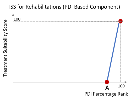
Typically, the value of node point “A” should be set within the range of 95% to 98% so ensure that Rehabilitations target the 5% of elements that have the most structural distress. However, the recommended way to set the value is to use the value as a variation parameter in a Goal Seek model. This will help you to select a value that optimises available funds over the long term.
Adjustment for Rut Depth Because the above-noted formula for TSS calculation only depends on the Pavement Distress Index, an adjustment is made to ‘boost’ the TSS calculated for Rehabilitation when there is excessive rut on the element.
The rut boost factor is calculated by taking the amount of rut above the specified rut threshold, and then multiplying that value by a ‘boosting factor’. Both the Rut Threshold and the Boost Factor can be respectively controlled by means of lookup parameters ‘rehab_excess_rut_thresh’ and ‘rehab_excess_rut_fact’ in the ‘treatment_suitability_scores’ lookup set.
Typically, you will want to set the value for ‘rehab_excess_rut_thresh’ to something in the range of 15mm to 25mm. The value for the excess multiplier ‘rehab_excess_rut_fact’ should be in the range 1 to 10. Making the latter value too high will lend undue weight to sites with high rut depth even when the PDI is relatively low.
See this page for more details on lookup values related to Treatment Suitability Scores.
Holding Action TSS Calculation
For holding actions, the initial TSS is also calculated on the basis of the PDI Rank relative to the rest of the network. A piecewise linear model is used to convert the PDI rank to an initial TSS score.
The shape of the TSS curve for holding actions is shown in Figure 2. As shown, the TSS calculation depends on three nodes, all of which can be adjusted in the lookup table:
Node “B” - PDI rank below which TSS for holding actions becomes zero. Maps to lookup parameter ‘holding_pdi_rank_pt1’ in the ‘treatment_suitability_scores’ lookup set.
Node “C” - PDI rank at which TSS for holding actions becomes 100. Maps to lookup parameter ‘holding_pdi_rank_pt2’ in the ‘treatment_suitability_scores’ lookup set.
Node “D” - TSS assigned when the PDI rank is 100% (highest on the network). Maps to lookup parameter ‘holding_pdi_rank_pt3’ in the ‘treatment_suitability_scores’ lookup set.
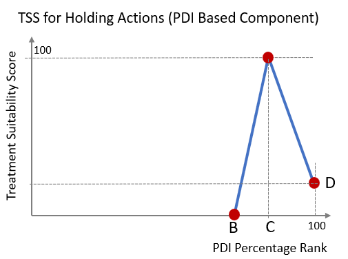
A typical value for Node point “B” would be 90%, indicating that holding actions are considered for elements for which the PDI is in the top 10%.
A typical value for Node point “C” would be 95%, indicating that holding actions are ideally suited for elements for which the PDI is around 95%.
A typical value for Node point “D” would be 30, indicating that the element the highest PDI on the network is much less suited for holding action than a Rehabilitation (which will get an initial TSS of 100 for a PDI rank of 100% - see Figure 1).
The TSS curve for holding actions seeks to position holding actions on segments with significant structural distress, but reduces the suitability of holding actions for elements that move into ‘rehabilitation territory’ as defined by Figure 1.
The above calculationn of TSS can be overriden by two guardrail thresholds to ensure that Holding actions are not considered when there is excessive structural distress on Asphalt surfacings or when there is excessive rut.
Adjustment for Excessive Rut
The TSS calculated based on node points “B”, “C” and “D” will be overridden if the Rut Depth is above the threshold specified by lookup parameter ‘holding_max_rut’ in the ‘treatment_suitability_scores’ lookup set.
If the Rut depth on the element is above this value, the TSS will be set to zero regardless of the PDI Ranking.
Adjustment for Excessive Structural Distress - Asphalt Surfacings
The TSS calculated based on node points “B”, “C” and “D” will be overridden if the PDI on asphalt-surfaced elements is above the threshold specified by lookup parameter ‘holding_max_pdi_ac’ in the ‘treatment_suitability_scores’ lookup set.
This threshold can be used as a throttle or gate to control holding actions on asphalt surfacings. It should be adjusted with due consideration given to the reset values assigned after holding actions. For example, setting this threshold too high will mean that the S-curve reset will be such that distress will rapidly appear again after treatment.
Preservation TSS Calculation
The TSS for Preservation treatments (i.e. Chipseals without pre-seal repairs or Thin AC without preceding Heavy Maintenance) is determined based on a set of thresholds to prevent such treatments from being placed when there is excessive structural distress or rutting.
The thresholds that control the TSS for Preservation treatments are controlled by the following parameters in the ‘treatment_suitability_scores’ lookup set:
‘preserve_max_pdi_chipseal’ - maximum PDI at which preservation treatment will be considered on Chipseal surfacings.
‘preserve_max_pdi_ac’ - maximum PDI at which preservation treatment will be considered on Asphalt surfacings.
‘preserve_max_rut’ - maximum rut depth at which preservation treatments should be considered.
‘preserve_min_sla’ - minimum Surface Life Achieved (%) at which Preservation treatments should be considered. Use this threshold to ensure that Preservation is only reserved for elements that are close to or above their expected surface life.
The trigger process for Preservation treatments is such that first all of the above thresholds are checked. If any of these threshold conditions are not met, a Preservation treatment is not considered.
If all of the above thresholds are met, the TSS is calculated on the basis of the piecewise linear curve shown in Figure 3. Node point ‘E’ in Figure 3 can be controlled by lookup parameter ‘preserve_sdi_rank’ in the ‘treatment_suitability_scores’ lookup set.
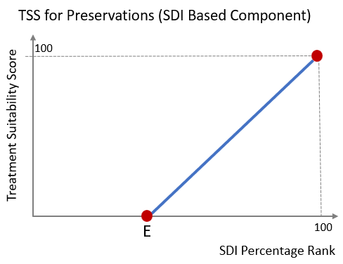
Essentially, the trigger and TSS calculation process for Preservation seeks to first ensure that Preservation treatments are not considered when (a) it would rapidly fail due to excessive distress or rut; or (b) it is not yet urgent and the funding is better applied on other parts of the network.
Secondly, once the above conditions are checked, the piecewise linear model in Figure 3 seeks to assign a higher score to elements that have higher surfacing distress (e.g. Flushing or Scabbing).